Dynamic Compaction Equipment improves weak ground through repeated, high-energy impacts. A crane lifts a heavy steel pounder, then releases it onto the soil. Each strike leaves a crater. Across a treatment area, planned impact points form a visible grid. The process can densify loose granular soils and help prepare sites for foundations, roads, and industrial facilities.
Federal Highway Administration guidance describes typical pounder weights of about 10 to 30 tonnes and drop heights of roughly 10 to 30 metres. These ranges are not universal specifications. Soil type, groundwater, nearby structures, and required improvement depth all affect the equipment and operating plan. The FHWA’s *Ground Improvement Methods Reference Manual* provides technical guidance on assessing and applying ground-improvement methods. Site investigation and trial sections remain essential; a weight-and-height calculation alone cannot predict every field result.
Louis Menard, the French engineer associated with developing dynamic compaction, is often linked to the method’s central idea: improve ground by applying controlled impact energy. This is a paraphrase, not a verified direct quotation. The distinction matters. Equipment selection is not simply about choosing the heaviest pounder. Operators must control drop height, impact spacing, and sequence, while monitoring vibration and surface response. Some sites also need a lighter finishing phase to close impact craters. The work can look straightforward. The engineering is not. Understanding the equipment means understanding how its energy reaches the ground—and where that energy may create practical limits.
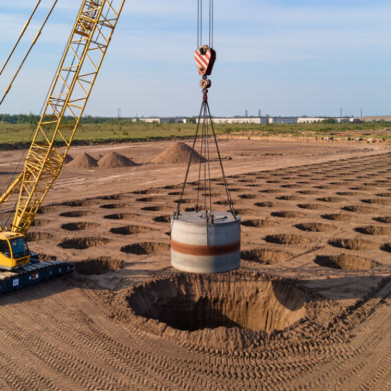
Dynamic compaction equipment uses a heavy steel weight, a lifting system, and a crane or purpose-built rig to improve ground strength. The weight is raised and released from a planned height onto the soil. Repeated impacts send energy below the surface, rearranging loose particles and reducing open spaces between them. The result can be denser ground with less risk of later settlement.
It is blunt work. Crews usually follow a marked grid, adjusting the drop height, impact count, and spacing to suit the site. They may track crater depth, surface movement, and vibration during treatment. These observations help show whether the ground is responding as expected, though conditions can vary across a small area. Dynamic compaction is often considered for loose granular soils, reclaimed ground, or some types of fill before construction. It is less predictable in very soft, saturated, or highly cohesive soils, where energy may not travel effectively. A careful site assessment matters; the method is powerful, but it is not a universal fix.

Dynamic compaction equipment improves weak ground by repeatedly dropping a heavy steel tamper onto the surface. Its main components work together to lift, release, and monitor each impact. A crawler crane or purpose-built carrier provides a stable working platform. The lifting rope raises the tamper to a set height, while a release system lets it fall under gravity. Impact energy drives soil particles closer together.
The tamper is usually a thick steel plate or block. Its weight and shape affect how energy reaches the ground. A guide frame may help control its path, though some machines operate without one. The operator uses cab controls to set the lift height and drop sequence. Sensors or survey equipment can track impact locations and surface settlement. The ground still needs assessment; equipment settings alone cannot show whether deeper layers are uniform. Results vary.
Tips: Check rope condition, release function, and the work area before lifting. Keep people clear of the drop zone. Record drop locations and visible settlement, such as a fresh crater or raised soil around the impact. These details help crews adjust the next passes, but field judgment remains important.
| Component | Main Function | How It Works in the Compaction Process |
|---|---|---|
| Crawler crane or other lifting machine | Raises and positions the tamper above designated drop points. | The machine moves the tamper into position and lifts it to the specified drop height. Its capacity and configuration must suit the tamper weight and operating requirements. |
| Heavy tamper (drop weight) | Transfers impact energy into the ground. | The tamper is lifted and released so it falls under gravity onto the ground surface. Its mass, shape, and drop height are selected for the project’s ground conditions and treatment objectives. |
| Lifting cable or hoist line | Connects the lifting machine to the tamper and supports lifting. | The line raises the tamper between drops. It is inspected and used within its rated working capacity, with connections secured according to the equipment and site procedures. |
| Release or drop mechanism | Controls the release of the tamper at the intended height. | The mechanism disengages the lifting connection or otherwise releases the weight, allowing a controlled free fall. Release arrangements vary by equipment design. |
| Guide frame or stabilizing arrangement | Helps keep the tamper aligned during lifting and release. | Where fitted, guides or stabilizing components limit unwanted movement and help the weight land near the planned impact point. Not all configurations use the same arrangement. |
| Operator controls and visibility aids | Allow the operator to position the machine, raise the weight, and carry out the drop cycle. | Controls operate the lifting and release functions. Clear communication with ground personnel helps maintain the exclusion zone and coordinate movement between impact points. |
| Power and hydraulic systems | Supply energy to the crane or lifting equipment and its operating functions. | The engine and associated mechanical, hydraulic, or electrical systems power machine travel, lifting, and controls, depending on the equipment design. |
| Monitoring and survey equipment | Records impact locations and supports control of the treatment sequence. | Survey markers, positioning tools, and site records can be used to track drop points, passes, drop heights, and the number of blows applied at each location. |
| Safety systems and work-zone controls | Reduce risks associated with suspended loads, falling weights, and ground movement. | Inspections, alarms or communication procedures, exclusion zones, stable working platforms, and adherence to the lift plan help keep personnel clear of the operating area. |
Dynamic compaction uses a heavy weight, lifted by a crane and dropped onto prepared ground. Each impact sends energy through loose soil, helping particles settle into a denser arrangement. Work begins with a geotechnical review: crews check soil layers, groundwater, nearby structures, and buried utilities. A test area can show how far the treatment reaches. This part may feel less exact than the drawings suggest.
Tips: Keep the impact zone clear, and check that the crane setup remains level. Record drop height and impact locations.
The crew marks a grid across the site, then drops the weight at planned points. Craters form after repeated impacts. Workers fill them with suitable material before the next pass, which may use different drop spacing or energy. Operators watch for uneven settlement, excessive vibration, or changes in ground response. These signs can mean the pattern needs adjustment. Not every area compacts evenly. After treatment, engineers may use field tests to assess density or stiffness and decide whether more impacts are needed. Test results matter more than appearance alone.
Before dynamic compaction begins, a geotechnical investigation should identify soil layers, groundwater depth, and likely settlement. The method often suits loose granular soils and uncontrolled fill, where repeated weight drops can rearrange particles. Fine, saturated soils may respond differently. Excess pore pressure can slow improvement, so testing and engineering judgment matter.
Site preparation starts with a level, stable working platform that can support the crane and its travel. Remove debris and mark buried utilities, drainage lines, and nearby structures. Keep clear records of existing cracks or ground movement. Vibration and flying debris are real concerns. Not every site qualifies.
Groundwater close to the surface may require drainage or a revised compaction sequence. A trial area can help establish drop height, spacing, and the number of passes before full production. Survey points and settlement readings reveal how the ground responds. They also catch problems early. Plans sometimes need adjustment; actual soil rarely matches every assumption in a report. Project-specific review by a qualified geotechnical professional helps set safe limits and confirm whether the treated ground meets design requirements.
Dynamic compaction densifies soil by repeatedly dropping a heavy steel weight from a crane. Each impact sends energy through the ground, rearranging loose particles and reducing voids. Drop height, tamper mass, and impact spacing are adjusted to suit site conditions.
The method is commonly used on large areas of loose fill, reclaimed land, ports, industrial sites, and building pads. It may also improve some collapsible soils before construction. On site, crews mark a grid and work through it in stages; fresh craters and displaced soil are part of the process. It is not universal.
Fine-grained soils that stay saturated may respond poorly because excess pore water pressure dissipates slowly. Nearby buildings, buried utilities, and sensitive equipment can be affected by vibration, noise, or falling debris. Groundwater depth and soil layers also influence how deeply and evenly the treatment works. A trial section, field testing, and settlement checks help verify the design, though results can still vary across a site. Engineers should set exclusion zones and monitor vibration, rather than assume a planned drop pattern will perform identically everywhere.
Energy is calculated as mass × gravity × drop height (E = mgh). These are illustrative equipment configurations, not measured performance ratings.
How it works: A crane lifts a heavy pounder and releases it onto the ground. Repeated impacts transmit energy into the soil, densifying suitable granular deposits or helping collapse voids in certain fill materials.
Common applications: Ground improvement for building, road, and port projects. Limitations: Performance depends on soil type, groundwater, depth, and site conditions; vibration, noise, nearby structures, and less-effective treatment of some fine-grained or saturated soils may constrain use. Actual energy delivered to the ground is lower than the theoretical values shown.
